2012年7月31日星期二

Defining Your Variable Speed Drive Requirements – A Checklist


Here’s an essential truism – knowing what to ask for is key to getting what you want. What follows is a checklist, with comments as appropriate, intended to help you define your variable speed drive (VSD) needs and ensure you get exactly the drive your application requires.
Motor Data:
  • Full load amperage (from the motor nameplate)
This will typically be labelled as “F.L.A.” on AC induction motors; “ARM Amps” and “FLD Amps” on DC motors. Rated amperage, NOT horsepower, is used to properly size VSD’s, because the power electronics are sized to conduct a certain amount of current for a certain amount of time, which can vary for a given motor horsepower depending on torque required.
  • Rated phase, frequency and voltage
This information can again be found on the motor nameplate. Often AC motors are rated for dual frequency (50/60 Hz); if so, this information should be included on the nameplate. If you intend to operate such a motor above rated speed, take care to note any changes to Service Factor; the dual frequency rating usually means a lower Service Factor when supplied with power at the lower frequency. For DC motors, you will typically need to identify armature volts (often simply labelled “volts”) and field volts (“FLD volts”).
For single-phase motors, speed control options are limited to simple in-line resistors, older triac/variac controls, or very low horsepower/low torque adjustable frequency controls. In many cases, if adjustable speed is desired for single-phase motors above about 2 HP, it will be less costly to replace the motor with a three-phase model.
  • Inverter Duty rating
AC motors designed in compliance with NEMA MG-1 Parts 30 and 31 are suitable for use with VSDs because of their inherently higher voltage withstand capabilities. Many, but not all, of these motors will be labelled as such. If you have a motor built more than 20 years ago, and/or operated regularly for the last 10 years, it is prudent to test the motor’s insulation system prior to deciding to control it with a VSD. Ideally, the insulation system will be capable of withstanding voltage levels in compliance with MG-1 standards (1600 volts for a 460V motor); lesser capabilities should be assessed to determine whether drive output filters, or worst case a new motor, might be needed.
  • Rated speed and desired turn-down
Turn-down is defined as the ratio of lowest operating speed to rated (base) speed. For example, a 20:1 turn-down for a 1,800 rpm motor would mean a lowest desired speed of 1,800/20 = 90 rpm. Most modern drives are readily capable of excellent speed regulation for turn-downs of 1000:1 or higher, so this ratio is more critical as related to self-cooled  (“air-over”) motors. When looking for a drive to operate a motor continuously at a speed of less than about 60% of rated, care must be taken to ensure that the motor does not overheat.
  Application Data:
  • Incoming (supply) phase, frequency and voltage
Drives can typically accommodate voltage ranges of +10/-15% and frequency ranges of +/-5%.
In cases where the available supply is single-phase, VSDs can be used to “add a phase” to produce three-phase output. This comes at a cost, however; VSDs capable of accepting a single-phase input have more robust converter and DC bus sections to allow longer rectifier firing times and higher magnitudes of DC ripple without over-heating. Some smaller drives – up to about 5 HP – are manufactured this way; in other cases, the VSD output current must be de-rated by 50% when fed with single-phase. In effect, this means that for a 20 HP load, a 40 HP drive needs to be specified.
  • Ambient environment for drive installation
Is the area in which the drive will be installed climate controlled? Protected from access by unauthorized personnel? Subjected to moisture/dust/corrosives? These factors and others must be considered when specifying an enclosure/suitable protection for the drive. Most standard drives are rated IP00 (open chassis), IP20 (finger-protected),  or IP21 (NEMA 1/UL type 1); other protection is optional (and at additional cost).
  • Load torque requirements
In order to define starting (breakaway) torque needed, it is helpful to know, at a minimum, the load torque profile. Variable torque (a.k.a. quadratic torque) applications demand less momentary overload capacity of the drive, so normal (or light) duty drives can be specified for these applications. Constant torque loads, on the other hand, usually require heavy-duty rating to accommodate the higher starting torque.
  • Motor lead length
This is the length of motor leads from the VSD output to the motor, not the linear distance of separation between the VSD and motor. Because of the high-speed switching of drive output electronics, longer leads increase radiated noise and voltage levels seen at the motor terminals. Leads longer than about 50 meters mean that the need for output filters on the VSD should be considered.
  • Single motor or multi-motor application
A VSD can supply multiple motors provided it is rated for at least the sum of the full-load amperages of all the connected motors. However, there are other application considerations, including motor protection and starting profiles, which require a more detailed analysis of the application before the drive can be specified. A qualified engineer/designer should be consulted.
The above represent the bare essentials needed to properly specify a drive for a given motor application. Other considerations include, among others, the need for electromagnetic interference reduction, impacts of harmonic distortion caused by the drive’s electronics on sensitive nearby equipment, process network communications. These are extensive topics in and of themselves and are fodder for future columns.


Regards,
Simon Fan
VTdrive Technologies
NEMA AC Motor Speed/Torque Characteristics


NEMA MG 1 assigns code letters to AC induction motor designs to indicate relationships between speed and torque. These relationships reflect the torque capabilities of various motor designs from zero (locked rotor) to synchronous speed. Why is knowing the torque characteristics of a motor important? Well, the most obvious reason is to ensure that the motor’s rated torque can supply the force needed to drive the load. This must be considered at all operating speeds – at start-up, the motor’s starting torque (also called “locked rotor” or “breakaway” torque) must be sufficient to move the load in order to avoid stalling the motor; and while running, the load torque requirements must not exceed the motor’s breakdown torque (also known as maximum or “pull-out” torque) or else the motor will see a steep drop in speed and rapid current and temperature rise.
For 3-phase motors up to 500 hp, there are basically three classes of speed/torque designs: A & B; C; and D. Let’s examine each in more detail; you can find representative curves and data in the figures below:
  • A & B: these are similar in characteristics, differing principally in terms of starting current. Primarily due to the relatively low impedance of the rotor, Design A motors have a higher starting current than Design B. ‘B’ motors are by far the most common of all the designs and are considered general purpose because of their mid-level starting torque and low starting current draw. Depending on motor size and speed, minimum breakaway torque range is approximately 150-200% of rated torque. Slip, defined as the percentage difference between synchronous speed and rated speed and needed for the induction motor to generate any torque in the first place, is low (less than 5%). Typical applications for such motors include fans, blowers, centrifugal pumps and compressors, and motor-generator sets where starting torque requirements are not high.
  • C: this motor uses a rotor winding configuration intended to increase starting torque while maintaining a low starting current. As a result, minimum breakaway torque requirements for these motors range from approximately 200-275% of rated torque. Slip is again low (less than 5%). Typical applications include conveyors, crushers, agitators, and reciprocating compressors.
  • D: these motors are used where very high starting torque is required. Motors are selected based on the slip needed to match the load. Starting current is again low, and slip can range from 5-13%. Because of this, relative efficiency of these motors is the lowest of the group. You will find these motors supplying high-inertia loads such as punch presses, shears, cranes, hoists, and elevators.
It should be noted that the above classes define minimum ratings. In the competitive marketplace, many motor manufacturers have chosen to go NEMA one better by designing motors which exceed these ratings. For instance, many Design B motors actually have locked rotor torques equivalent to Design C motors. Manufacturers are willing to invest more in motor construction to hit target markets while not facing the need to meet all NEMA minimum classification requirements. It is prudent, therefore, to examine motor specifications closely before deciding on one based solely on classification.
If you would like to discuss your motor application in detail, please contact us at info@vtdrive.com, or visit our websiteswww.VTdrive.com. We’d be glad to assist you in ensuring you select the right motor for your needs. If you would like to share any of your own perspectives on motor applications with your fellow readers, please visit the Comments section of this blog. Please also note that we’ve elected to change how often this blog is issued to every two weeks;  join us in early August for the next edition. We’ll see you then.

Regards,
Simon Fan
VTdrive Technologies
Bearing relubrication is key to longer AC Motor life


The increasing importance accorded to the maintenance of electric motors across all industry sectors is being driven by the requirement to guarantee trouble-free operation in what is a highly pressurized climate for manufacturing.
Because of this, many manufacturers have invested in motor monitoring and protection systems whose function is to reduce the frequency of maintenance intervals for electric motors, and also the incidence of motor failures.
These monitoring and protection measures, whilst effective, are not cheap.
Moreover, they do not provide a total solution, more basic initiatives, such as the planned relubrication of motor bearings at regular intervals, being far more effective over the life of the motor.
Relubrication intervals are the function of a number of bearing factors including:
bearing type, operating speed and temperature, type of grease and type of bearing housing.
Helpfully, in most instances the respective interval may be obtained with the use of graphs supplied by bearing suppliers. 
These use lithium-based soap grease as a reference (reference temperature is 70C) and recommend that the relubrication interval be reduced by half for every 15C of temperature increase - this in respect of the maximum temperature limit allowed by the grease.
As an example, VTdrive uses Polyrex EM grease in its IEC 225 to 355 frame motors (NEMA 364T to 5877) with a temperature reference grease of 85C. Therefore, when a bearing is operating at 100C, the lubrication interval indicated on the maintenance manual supplied with the motors must be reduced by half.
It is important to know that relubrication intervals are defined based on tests that do not allow for any ingress of water and/or solid contaminants into the motor. In cases where motors are subject to such contaminants then careful periodic cheeks must be carried out and the grease replaced more often to maintain its efficiency. 
The process of replacing and relubricating is a critical one, requiring special care to achieve the levels of bearing performance that extend bearing life.
In general four key recommendations need to be observed.
  1. The grease should be stored in a proper room to avoid penetration of contaminants. Additionally, before relubricating a motor, clean the grease nipple. Whenever possible, motors fitted with a grease fitting must be relubricated with the motor running.
    If not, pump in half of the grease fill recommended in the motor manual, run the motor for a minute, switch it off and then pump in the remaining grease. Motors not designed with a grease fitting must have the bearing carefully removed for relubrication.
  2. All grease must be removed and the bearing housing carefully cleaned with the application of kerosene or diesel. When regreasing, force the grease to penetrate into bearing races and all other internal orifices.
  3. It is quite important to spin the bearing while relubricating it so as to ensure proper grease penetration, hence avoiding noisy operation. The heating temperature when mounting the bearings cannot exceed 90C, as this will affect the grease adversely resulting in a reduction of bearing life.
  4. In cases where the bearing has been removed then heated and refitted to a shaft, it is important to avoid incorrect alignment by checking to determine if the internal bearing cap making a correct fit with the shaft.
If these recommendations are observed as part of a planned maintenance schedule, reliable motor operation will be ensured and also extended bearing life. As a result, maintenance costs will be reduced and unexpected - and costly - production failures will be avoided.

                               Technology originated from EMERSON and HUAWEI
Simon Fan Sales Manager
ShenZhen VTdrive Technology Co.,Ltd.
Mail:simon.fan@vtdrive.com
Tel:+86-0755-23060667
Fax:+86-0755-33671802
Skype:simon.fan0611
Address:3F&4F, Xihe Industrial Zone,
TangTou Load, Shiyan Town,
Baoan District, Shenzhen, China.

How to Maintain a Variable Frequency Drive?


How To Maintain a VFD
By: Dave Polka
Do you know how to maintain Variable Frequency Drives (VFDs)? Doing so is easier than you might think. By integrating some simple, logical steps into your preventative maintenance program, you can ensure your drives provide many years of trouble-free service. Before looking at those steps, let's quickly review what a VFD is and how it works
A Quick Overview
A VFD controls the speed, torque and direction of an AC Induction motor. It takes fixed voltage and frequency AC input and converts it to a variable voltage and frequency AC output. See Training Note "What is a VFD?" for a more detailed description of VFD concepts and operating principles. In very small VFDs, a single power pack unit may contain the converter and inverter. 
Fairly involved control circuitry coordinates the switching of power devices, typically through a control board that dictates the firing of power components in the proper sequence. A microprocessor or Digital Signal Processor (DSP) meets all the internal logic and decision requirements. 
From this description, you can see a VFD is basically a computer and power supply. And the same safety and equipment precautions you'd apply to a computer and to a power supply apply here. VFD maintenance requirements fall into three basic categories:
  • keep it clean;
  • keep it dry; and
  • keep the connections tight.
Let's look at each of these. 
Keep it Clean
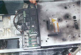
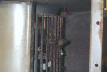
Most VFDs fall into the NEMA 1 category (side vents for cooling airflow) or NEMA 12 category (sealed, dust-tight enclosure). Drives that fall in the NEMA 1 category are susceptible to dust contamination. Dust on VFD hardware can cause a lack of airflow, resulting in diminished performance from heat sinks and circulating fans (Photo 1).
Photo 1, Fan Injecting Dust into Drive Enclosure
Dust on an electronic device can cause malfunction or even failure. Dust absorbs moisture, which also contributes to failure. Periodically spraying air through the heat sink fan is a good PM measure. Discharging compressed air into a VFD is a viable option in some environments, but typical plant air contains oil and water. To use compressed air for cooling, you must use air  that is oil-free and dry or you are likely to do more harm than good. That requires a specialized, dedicated, and expensive air supply. And you still run the risk of generating electrostatic charges (ESD). 
A non-static generating spray or a reverse-operated ESD vacuum will reduce static build-up. Common plastics are prime generators of static electricity. The material in ESD vacuum cases  and fans is a special, non-static generating plastic. These vacuums, and cans of non-static  generating compressed air, are available through companies that specialize in static control equipment. 
Keep it Dry
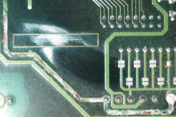
In Photo 2 you can see what happened to a control board periodically subjected to a moist environment. Initially, this VFD was wall-mounted in a clean, dry area of a mechanical room and moisture was not a problem. However, as is often the case, a well-meaning modification led to problems. 
In this example, an area of the building required a dehumidifier close to the mechanical room.  Since wall space was available above the VFD, this is where the dehumidifier went. Unfortunately, the VFD was a NEMA 1 enclosure style (side vents and no seal around the cover). The obvious result was water dripping from the dehumidifier into the drive. In six months, the VFD accumulated enough water to produce circuit board corrosion.
 Photo 2, Corrosion on Board Traces Caused by Moisture
Photo 2, Corrosion on Board Traces Caused by Moisture
What about condensation? Some VFD manufacturers included a type of "condensation protection" on earlier product versions. When the mercury dipped below 32 degrees Fahrenheit, the software logic would not allow the drive to start. VFDs seldom offer this protection today. If you operate the VFD all day every day, the normal radiant heat from the heatsink should prevent condensation. Unless the unit is in continuous operation, use a NEMA 12 enclosure and thermostatically controlled space heater if you locate it where condensation is likely. 
Keep Connections Tight
While this sounds basic, checking connections is a step many people miss or do incorrectly - and the requirement applies even in clean rooms. Heat cycles and mechanical vibration can lead to sub-standard connections, as can standard PM practices. Retorquing screws is not a good idea, and further tightening an already tight connection can ruin the connection (see Sidebar). 
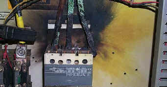
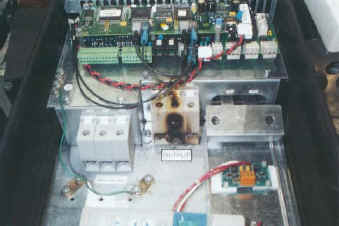
Bad connections eventually lead to arcing. Arcing at the VFD input could result in nuisance over voltage faults, clearing of input fuses, or damage to protective components. Arcing at the VFD output could result in over-current faults, or even damage to the power components. Photos 3 and 4 show what can happen. 
Loose control wiring connections can cause erratic operation. For example, a loose START/STOP signal wire can cause uncontrollable VFD stops. A loose speed reference wire can cause the drive speed to fluctuate, resulting in scrap, machine damage, or personnel injury.
Photo 3, Arcing Caused by Loose Input Contacts
Photo 4, Arcing Caused by Loose Output Contacts
Re-torquing - A Screwy Practice
Although "re-torquing" as a way of checking tightness is common in many PM procedures, it violates basic mechanical principles and does more harm than good. A screw has maximum clamping power at a torque value specific to its size, shape, and composition. Exceeding that torque value permanently reduces the clamping power of that screw by reducing its elasticity and deforming it. Loosening and then re-torquing still reduces elasticity, which still means a loss of clamping power. Doing this to a lock washer results in a permanent 50% loss. What should you do? Use an infrared thermometer to note hot connections. Check their torque. If they have merely worked loose, you can try retightening them. Note which screws were loose, and be sure to give them an IR check at the next PM cycle. If they are loose again, replace them. Finally, don't forget the "tug test." This checks crimps, as well as screw connections. Don't do this with the drive online with the process, though, or you may cause some very expensive process disturbances. 
Additional Steps
  1. As part of a mechanical inspection procedure, don't overlook internal VFD components. Check circulating fans for signs of bearing failure or foreign objects - usually indicated by unusual noise or shafts that appear wobbly.
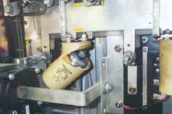
  2. Inspect DC bus capacitors for bulging and leakage. Either could be a sign of component stress or electrical misuse. Photos 5 and 6 show fan and capacitor stress problems.
    Photo 5, Foreign Object in Fan
    Photo 5, Foreign Object in Fan
  3. Take voltage measurements while the VFD is in operation. Fluctuations in DC bus voltage measurements can indicate degradation of DC bus capacitors. One function of the capacitor bank is to act as a filter section (smoothing out any AC ripple voltage on the Bus). Abnormal AC voltage on the DC bus indicates the capacitors are headed for trouble. 

    Most VFD manufacturers have a special terminal block for this type of measurement and also for connection of the dynamic braking resistors. Measurements more than 4VAC may indicate a capacitor filtering problem or a possible problem with the diode bridge converter section (ahead of the bus). If you have such voltage levels, consult the VFD manufacturer before taking further action. 

    With the VFD in START and at zero speed, you should read output voltage of 40VAC phase-to-phase or less. If you read more than this, you may have transistor leakage. At zero speed, the power components should not be operating. If your readings are 60VAC or more, you can expect power component failure. 
  4. What about spare VFDs? Store them in a clean, dry environment, with no condensation allowed. Place this unit in your PM system so you know to power it up every 6 months to keep the DC bus capacitors at their peak performance capability. Otherwise, their charging ability will significantly diminish. A capacitor is much like a battery-it needs to go into service soon after purchase or suffer a loss of usable life.
    Photo 6, Capacitor Failure
    Photo 6, Capacitor Failure
  5. Regularly monitor heat sink temperatures. Most VFD manufacturers make this task easy by including a direct temperature readout on the Keypad or display. Verify where this readout is, and make checking it part of a weekly or monthly review of VFD operation. You wouldn't place your laptop computer outside, on the roof of a building or in direct sunlight, where temperatures could reach 115 degrees Fahrenheit or as low as -10 degrees Fahrenheit. A VFD, which is basically a computer with a power supply, needs the same consideration. Some VFD manufacturers advertise 200,000 hours-almost 23 years-of Mean Time Between Failures (MTBF). Such impressive performance is easy to obtain, if you follow these simple procedures. 

                             Technology originated from EMERSON and HUAWEI
Simon Fan Sales Manager
ShenZhen VTdrive Technology Co.,Ltd.
Mail:simon.fan@vtdrive.com
Tel:+86-0755-23060667
Fax:+86-0755-33671802
Skype:simon.fan0611
Address:3F&4F, Xihe Industrial Zone,
TangTou Load, Shiyan Town,
Baoan District, Shenzhen, China.


This information has been provided by: ABB Inc. - Drives and Power Electronics

What is a Variable Speed Drive? How does a VSD Work?


How Drive Changes Motor Speed
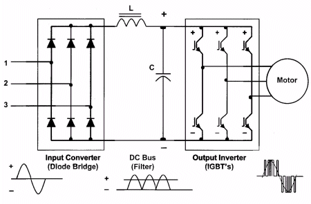
Just how does a drive provide the frequency and voltage output necessary to change the speed of a motor? That's what we'll look at next. Fig. 6 shows a basic PWM drive. All PWM drives contain these main parts, with subtle differences in hardware and software components.
Figure 6, Basic PWM Drive Components
Although some drives accept single-phase input power, we'll focus on the 3-phase drive. But to simplify illustrations, the waveforms in the following drive figures show only one phase of input and output.
The input section of the drive is the converter. It contains six diodes, arranged in an electrical bridge. These diodes convert AC power to DC power. The next section-the DC bus section-sees a fixed DC voltage.
The DC Bus section filters and smoothes out the waveform. The diodes actually reconstruct the negative halves of the waveform onto the positive half. In a 460V unit, you'd measure an average DC bus voltage of about 650V to 680V. You can calculate this as line voltage times 1.414. The inductor (L) and the capacitor (C) work together to filter out any AC component of the DC waveform. The smoother the DC waveform, the cleaner the output waveform from the drive.
The DC bus feeds the final section of the drive: the inverter. As the name implies, this section inverts the DC voltage back to AC. But, it does so in a variable voltage and frequency output. How does it do this? That depends on what kind of power devices your drive uses. If you have many SCR (Silicon Controlled Rectifier)-based drives in your facility, see the Sidebar. Bipolar Transistor technology began superceding SCRs in drives in the mid-1970s. In the early 1990s, those gave way to using Insulated Gate Bipolar Transistor (IGBT) technology, which will form the basis for our discussion. 
Switching Bus With IGBTs
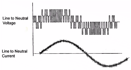
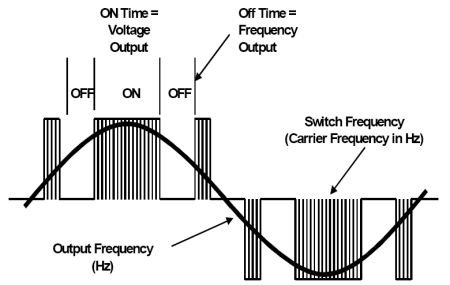
Today's inverters use Insulated Gate Bipolar Transistors (IGBTs) to switch the DC bus on and off at specific intervals. In doing so, the inverter actually creates a variable AC voltage and frequency output. As shown in Fig. 7, the output of the drive doesn't provide an exact replica of the AC input sine waveform. Instead, it provides voltage pulses that are at a constant magnitude.
Figure 7, Drive Output Waveform
The drive's control board signals the power device's control circuits to turn "on" the waveform positive half or negative half of the power device. This alternating of positive and negative switches recreates the 3 phase output. The longer the power device remains on, the higher the output voltage. The less time the power device is on, the lower the output voltage (shown in Fig.8). Conversely, the longer the power device is off, the lower the output frequency.
Figure 8, Drive Output Waveform Components
The speed at which power devices switch on and off is the carrier frequency, also known as the switch  frequency. The higher the switch frequency, the more resolution each PWM pulse contains. Typical switch frequencies are 3,000 to 4,000 times per second (3KHz to 4KHz). (With an older, SCR-based drive, switch frequencies are 250 to 500 times per second). As you can imagine, the higher the switch frequency, the smoother the output waveform and the higher the resolution. However, higher switch frequencies decrease the efficiency of the drive because of increased heat in the power devices. 
Shrinking cost and size
Drives vary in the complexity of their designs, but the designs continue to improve. Drives come in smaller packages with each generation. The trend is similar to that of the personal computer. More features, better performance, and lower cost with successive generations. Unlike computers, however, drives have dramatically improved in their reliability and ease of use. And also unlike computers, the typical drive of today doesn't spew gratuitous harmonics into your distribution system-nor does it affect your power factor. Drives are increasingly becoming "plug and play." As electronic power components improve in reliability and decrease in size, the cost and size of VFDs will continue to decrease. While all that is going on, their performance and ease of use will only get better. 
Sidebar: What if you have SCRs?
With the large installed base of SCRs, you might want to know how these operate. An SCR (originally referred to as a thyristor) contains a control element called a gate. The gate acts as the "turn-on" switch that allows the device to fully conduct voltage. The device conducts voltage until the polarity of the device reverses-and then it automatically "turns off." Special circuitry, usually requiring another circuit board and associated wiring, controls this switching.
The SCR's output depends on how soon in the control cycle that gate turns on. The IGBT output also depends the length of time the gate is on. However, it can turn off anytime in the control cycle, providing a more precise output waveform. IGBTs also require a control circuit connected to the gate, but this circuitry is less complex and doesn't require a reversal of polarity. Thus, you would approach troubleshooting differently if you have an SCR-based drive. 
                               Technology originated from EMERSON and HUAWEI
Simon Fan Sales Manager
ShenZhen VTdrive Technology Co.,Ltd.
Mail:simon.fan@vtdrive.com
Tel:+86-0755-23060667
Fax:+86-0755-33671802
Skype:simon.fan0611
Address:3F&4F, Xihe Industrial Zone,
TangTou Load, Shiyan Town,

Baoan District, Shenzhen, China.


This information has been provided by: ABB Inc. - Drives and Power Electronics

What is a Variable Frequency Drive? How does a VFD Work?


What is a VFD?
By: Dave Polka
You can divide the world of electronic motor drives into two categories: AC and DC. A motor drive controls the speed, torque, direction and resulting horsepower of a motor. A DC drive typically controls a shunt wound DC motor, which has separate armature and field circuits. AC drives control AC induction motors, and-like their DC counterparts-control speed, torque, and horsepower.
Application As An Example
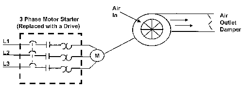
Let's take a brief look at a drive application. In Fig. 1, you can see a simple application with a fixed speed fan using a motor starter. You could replace the 3-phase motor starter with Variable Frequency Drive (VFD) to operate the fan at variable speed. Since you can operate the fan at any speed below its maximum, you can vary airflow by controlling the motor speed instead of the air outlet damper.
Figure 1, Fixed Speed Fan Application
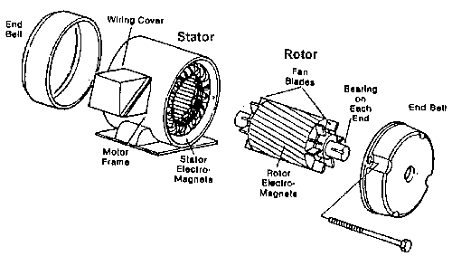
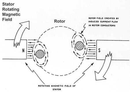
A drive can control two main elements of a 3-phase induction motor: speed and torque. To understand how a drive controls these two elements, we will take a short review of AC induction motors. Fig. 2 shows the construction of an induction motor. The two basic parts of the motor, the rotor and stator, work through magnetic interaction. A motor contains pole pairs. These are iron pieces in the stator, wound in a specific pattern to provide a north to south magnetic field.
Figure 2, Basic Induction Motor Construction
Figure 3, Operating Principles of Induction Motor
With one pole pair isolated in a motor, the rotor (shaft) rotates at a specific speed: the base speed. The number of poles and the frequency applied determine this speed (Fig. 4). This formula includes an effect called "slip." Slip is the difference between the rotor speed and the rotating magnetic field in the stator. When a magnetic field passes through the conductors of the rotor, the rotor takes on magnetic fields of its own. These rotor magnetic fields will try to catch up to the rotating fields of the stator. However, it never does -- this difference is slip. Think of slip as the distance between the greyhounds and the hare they are chasing around the track. As long as they don't catch up to the hare, they will continue to revolve around the track. Slip is what allows a motor to turn. 
Motor Slip:
Shaft Speed =
120 X FP
- Slip
Slip for NEMA B Motor = 3 to 5% of Base Speed which is 1800 RPM at Full Load 
F = Frequency applied to the motor
P = Number of motor poles
Example:
Shaft Speed =
120 X 60 Hz4
- Slip
Figure 4, Induction Motor Slip Calculation
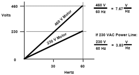
We can conveniently adjust the speed of a motor by changing the frequency applied to the motor. You could adjust motor speed by adjusting the number of poles, but this is a physical change to the motor. It would require rewinding, and result in a step change to the speed. So, for convenience, cost-efficiency, and precision, we change the frequency. Fig. 5 shows the torque-developing characteristic of every motor: the Volts per Hertz ratio (V/Hz). We change this ratio to change motor torque. An induction motor connected to a 460V, 60 Hz source has a ratio of 7.67. As long as this ratio stays in proportion, the motor will develop rated torque. A drive provides many different frequency outputs. At any given frequency output of the drive, you get a new torque curve.
Figure 5, Volts/Hertz Ratio
                             Technology originated from EMERSON and HUAWEI
Simon Fan Sales Manager
ShenZhen VTdrive Technology Co.,Ltd.
Mail:simon.fan@vtdrive.com
Tel:+86-0755-23060667
Fax:+86-0755-33671802
Skype:simon.fan0611
Address:3F&4F, Xihe Industrial Zone,
TangTou Load, Shiyan Town,
Baoan District, Shenzhen, China.


This information has been provided by: ABB Inc. - Drives and Power Electronics

Storende geluiden bij gebruik van een elektromotor met frequentieregelaar


Regelmatig krijg ik te horen, dat de elektromotor bij gebruik van een frequentieregelaar bij bepaalde frequenties een hoge pieptoon of jengeltoon laat horen.
De vraag is dan meestal: Wat is er aan de hand?

De stator van een elektromotor is opgebouwd uit lamellenpakketten met daar in de wikkelingen.
Deze lamellenpakketten kunnen op sommige plaatsen niet strak genoeg op elkaar zitten, zodat ze bij bepaalde frequenties gaan resoneren/in resonantie komen/met de snelheid van de frequentie gaan trillen.
Dat kan in sommige gevallen hinderlijke geluiden opleveren.
Nu zijn er frequentieregelaars, waarbij de frequentie, waarbij deze resonantie optreedt, uit te schakelen is, zodat de regelaar deze frequentie over slaat en het storende geluid beduidend minder wordt.
Ook heel vaak komt het voor, dat het op verschillende kleine frequentiegebiedjes gaat resoneren en dat dat niet meer uit te schakelen is.
U begrijpt al, dat het ligt aan de bouw van de stator van de motor.
Is er een andere motor aanwezig, dan zou dat een oplossing kunnen zijn.

Ook wel wordt de oplossing gezocht in het isoleren van het geluid van de motor.
Maar ook dat kan niet onder alle omstandigheden, want de motor moet wel zijn koeling blijven behouden.

Ook kan het wel eens verholpen worden met een andere frequentieregelaar.
Maar dat wordt dan experimenteren.

Een 1-2-3 oplossing voor dat probleem valt dus niet zo maar aan te dragen.


                             Technology originated from EMERSON and HUAWEI
Simon Fan Sales Manager
ShenZhen VTdrive Technology Co.,Ltd.
Mail:simon.fan@vtdrive.com
Tel:+86-0755-23060667
Fax:+86-0755-33671802
Skype:simon.fan0611
Address:3F&4F, Xihe Industrial Zone,
TangTou Load, Shiyan Town,
Baoan District, Shenzhen, China.

Toepassingen van de frequentieregelaar


Een frequentieregelaar kan voor verschillende doeleinden gebruikt worden, zoals snelheidsregeling van transportbanden en ventilatoren, hijsen en positionering van een motor.
Hier onder wordt in vogelvlucht de toepassing van een frequentieregelaar in een transportband en voor een opwikkelmachine besproken.

Snelheidsregeling van een transportband

Een transportband kan in snelheid geregeld worden zodat de producten tijdens het aan- en uitzetten niet omvallen en het is praktisch, als een band niet te snel of niet te langzaam draait. Om dit te voorkomen zorgt de frequentieregelaar er voor dat er langzaam versneld en gestopt wordt. Er wordt dus een langere acceleratie en deceleratie in de frequentieregelaar ingesteld en het toerental kan geregeld worden..

Koppelregeling voor opwikkelmachine

Om bijvoorbeeld draad op te wikkelen is het belangrijk dat er met een constante trekkracht getrokken wordt. Omdat de straal van de draad groter wordt, naarmate de spoel voller wordt, neemt ook de spanning op het draad toe. Om dit te voorkomen is de frequentieregelaar uitgerust met een koppelregeling.
De frequentieregelaar zorgt er voor dat de motor een bepaald toerental zal gaan draaien zodat de motor precies het ingestelde koppel levert.
Een frequentieregelaar is er dus om er voor te zorgen dat een draaistroommotor gelijkmatig aanloopt, hij voorkomt dat er hoge aanloopstromen optreden en de frequentieregelaar zorgt er voor dat de draaistroommotor het gewenste toerental geeft.
De frequentieregelaar werkt met behulp van gelijkrichting en wisselrichting.
Om storingen te voorkomen wordt er gebruik gemaakt van netfilters, om aan de CE normering te voldoen is dit zelfs verplicht.
Functies die op de meeste frequentieregelaars voorkomen zijn instelbare acceleratie- en deceleratietijd, koppeldetectie, stall prevention, slipcompensatie, beveiliging tegen oververhitting, koppelcompensatie, remmen door gelijkstroominjectie.
Het is dus verstandig een frequentieregelaar te gebruiken, vooral bij het aandrijven van grote machines. Dit kan een grote energiebesparing opleveren, doordat er een veel lagere aanloop stroom nodig is en de motor door de verschillende functies van de frequentieregelaar veel beter loopt.
De frequentieregelaar kan dus veel meer dan alleen het harder en zachter laten lopen van een motor.
Kijk ook bij: Energie besparen

                             Technology originated from EMERSON and HUAWEI
Simon Fan Sales Manager
ShenZhen VTdrive Technology Co.,Ltd.
Mail:simon.fan@vtdrive.com
Tel:+86-0755-23060667
Fax:+86-0755-33671802
Skype:simon.fan0611
Address:3F&4F, Xihe Industrial Zone,
TangTou Load, Shiyan Town,
Baoan District, Shenzhen, China.