2002 IEEE IAS Annual Meeting
Brian Thomas Boulter
Applied Industrial Control Solutions
231 Skyview Drive
Seven Hills, OH, USA 44131
Applied Industrial Control Solutions
231 Skyview Drive
Seven Hills, OH, USA 44131
© ApICS ® LLC 2000
Abstract- In web/strip processing lines, position loops are used to regulate dancers, accumulators, cutting shears, and for motion or positioning control in many other applications. Depending on the requirements of the application, a fast responsive torque regulator may or may not be required. This paper provides guidelines for the useful interpretation of AC/DC drive performance specifications as applied to positioning applications, from a drive system’s application perspective.
I. Introduction
As noted in [3], [4] the technical climate in today’s drive systems business markets has been inundated by drive vendor claims of ever improving drive performance specifications. The objective of this report is to bring those performance specifications that apply to positioning and motion control applications into technical focus, and provide the reader with a basis for correctly interpreting them from a SYSTEMS /APPLICATIONS perspective. A future paper will address performance issues associated with "cascaded" and "parallel", tension regulation schemes. Part I [3] dealt with speed regulation issues, Part II [4] dealt with torque/current regulation schemes.
It is hoped that the reader will walk away from this presentation with the tools required to sift through a given drive’s performance specifications, and glean from them those points that are truly of importance to the position/motion control application in question.
- Paper Overview
- Nomenclature
The paper is divided into four sections. The first section is composed of this introduction and the paper nemenclature, the second section defines a set of useful terms, the third section defines the most important drive specifications with respect to positioning and motion control, and methods of determining these criteria for a given drive system. A set of observations and conclusions are presented in the fourth section
| Per-Normal (PN) inertia [sec] | |
| PN Storage | |
| PN motor speed (1 = > Sb) | |
| PN motor torque (1 = > ti(R)) | |
| PN loss torque (1 = > ti(R)) | |
| Sb | motor rated speed [rpm] |
ti(R)
|
rated motor torque [N.m]
|
| Ti | down-stream strip tension [N] |
| Ti+1 | up-stream strip tension [N] |
| Ri | Roll diameter [m] |
| GRi | Gear ratio |
| wS | Speed Loop (SML) PI Lead Freq. [rad/sec] |
wP
|
Position Loop (PL) PI Lead Freq. [rad/sec]
|
wLD
|
PL Feedback L/L filter Lead Freq. [rad/sec]
|
wLG
|
PL Feedback L/L filter Lag Freq. [rad/sec]
|
wSML
|
SML bandwidth (crossover freq.) [rad/sec]
|
wPL
|
PL bandwidth (crossover freq.) [rad/sec]
|
zPL
|
PL closed loop tunable damping term
|
| KS | SML PI proportional gain |
| KP | PL PI proportional gain |
II. Some Useful Definitions
Several definitions that prove useful in understanding drive system positioning regulation performance criteria are, control loop bandwidth, per-normal Inertia, and per-normal storage.
Control Loop Bandwidth: Bandwidth is defined as the frequency at which the closed loop response of the controlled variable is attenuated 3 [db] from the set point. It is also approximated as the point at which the open loop gain of the system is unity and is called the "crossover" frequency.
Per-Normal Inertia: Per-normal (PN), or normalized, reflected inertia [sec] is the time in seconds that it takes to accelerate the motor and load inertia from zero speed to motor base speed (Sb) with motor rated torque (tRated) and the given reflected inertia (J). SI units:
 (0)
(0)
Per-Normal Storage (Fig. 1):
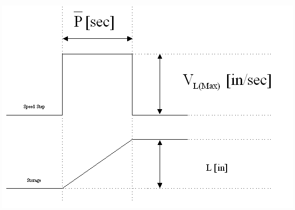
Fig. 1 Per-Normal Storage [sec]
In web/strip processing applications per-normal storage  is the time it takes (in [sec]) to integrate storage to L [in] with maximum (VL(MAX)) line speed. Note that Storage is not always equal to the full amount of material that can be stored in the position controlled mechanical system. In web/strip processing applications it is the amount of material that can be stored in the mechanical system over which the feedback varies from 0% to 100%. In other positioning applications it can be any controlled quantity over which the position feedback varies from 0% to 100%. This idea can be applied to all positioning and motion control systems.
 is the time it takes (in [sec]) to integrate storage to L [in] with maximum (VL(MAX)) line speed. Note that Storage is not always equal to the full amount of material that can be stored in the position controlled mechanical system. In web/strip processing applications it is the amount of material that can be stored in the mechanical system over which the feedback varies from 0% to 100%. In other positioning applications it can be any controlled quantity over which the position feedback varies from 0% to 100%. This idea can be applied to all positioning and motion control systems.
III. Interpreting Drive Performance Specifications That Apply To Positioning Systems
A. Architecture Description
Linear position regulators can be implemented as either cascaded or parallel major loops. The cascaded architecture (Fig.2) is implemented with a speed intermediate loop (SML). In this architecture, the position loop (PL) trims the SML which provides a reference to the current/torque minor loop (CML). The parallel architecture (Fig.3) provides a trim for the position major loop directly to the CML. In web/strip processing lines the trim is usually applied through the appropriate SML PI limit. By applying the control signal through the SML PI limit, the drive will not over-speed the motor if a strip or web break occurs during operation. Rather the drive will allow the motor to rotate at the given speed reference plus a small offset that is used to force the SML PI up against the limit.
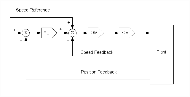
Fig. 2. Cascaded Position Loop Architecture.
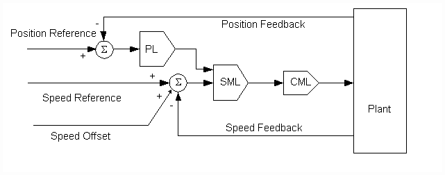
Fig. 3. Parallel Position Loop Architecture.
These regulation architectures are often used in conjunction with feedforward control strategies. This approach is taken in applications that require optimal trajectory tracking, typically in motion control applications. Following is a description of the feedforward terms.
B. Feedforward terms
Optimal trajectory tracking in motion control applications (such as cutting shears, cut-to-length and similar applications) require the implementation of feed-forward inertia and occasionally, friction (loss) compensation. These calculated feed-forward torque terms provide the extra torque needed to accelerate/decelerate the given inertia, and to provide compensation for friction/windage losses. They must be summed in with the current/torque minor loop (CML) reference.
The per-normal (PN) equation describing the summation of rotational forces at the motor shaft is given as:
 (1)
(1)
In terms of motor torque:
 (2)
(2)
where:
 = PN Inertia compensation torque
 = PN Friction compensation torque
 = PN tension drop torque
For optimal trajectory tracking, the torque reference to the drive should at least include inertia compensation, friction compensation is not as important in motion control applications as it is in torque (pseudo tension) regulation schemes.
The Inertia compensation term can be calculated based on the known line acceleration rate, and the inertia of the driven system. If the system inertia changes (such as in a winder) the inertia can be calculated based on known physical parameters.
C. Dynamic Accuracy (Bandwidth)
The dynamic accuracy of a cascaded position loop is constrained by the bandwidth of the speed intermediate loop. If no forcing is used in the position feedback (i.e. no lead/lag in the feedback), the maximum position loop bandwidth will be less than or equal to the bandwidth of the speed intermediate loop. If feedback forcing is used, the maximum bandwidth can be as high as 3 or 4 times the SML bandwidth.
The dynamic performance of a parallel position loop (properly configured and tuned) will only be limited by the noise sensitivity of the system. This may be identified using the analytical method described in [3]. Briefly, to maintain a constant bandwidth in the position loop as the inertia of the driven system increases, the gain of the position loop will have to increase proportionally. This leads to noise amplification, and places constraints on the position loop gain term based on the quality of the drive train mechanics and the amount of system noise [3]. The constrained gain term limits the bandwidth of the position loop.
For Cascaded Position Loops the bandwidth constraint in [3] is replaced with:
 (3)
(3)
For Parallel Position Loops the bandwidth constraint in [3] is replaced with:
 (4)
(4)
The tuning equations given below assume that the loops have been normalized. That is, that a unity reference maps to a maximum reference and will produce unity feedback. Under this assumption any of the sate variable quantities (such as speed, torque, position etc) will equal unity at their respective maximum value.
D. Static Accuracy (Resolution):
The static accuracy of a position loop is dependant on the quality of the feedback devices used. The same guidelines described in the static accuracy description in [4] apply.
E. Cascaded Positioning Loops
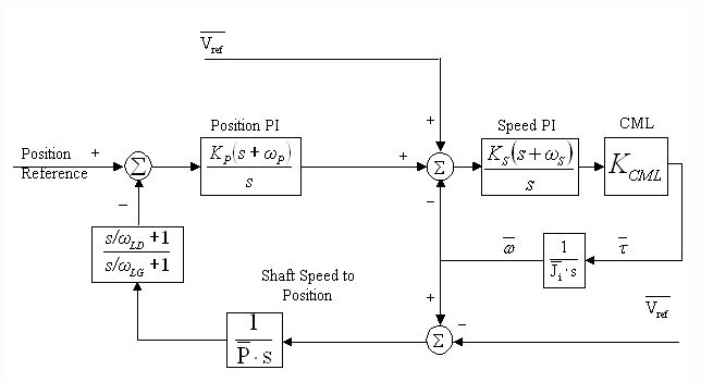
Fig. 4. Normalized Cascaded Position Loop
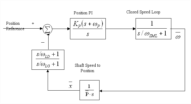
Fig. 5. Simplified Normalized Cascaded Position Loop
The cascaded architecture tuning is dependant on the bandwidth of the speed loop with which it is cascaded. The bandwidth of the speed loop may or may not vary depending on the application and the speed loop tuning strategy. A normalized linearized block diagram of a cascaded position loop is shown in Fig. 4. It can be shown that a closed speed loop with at least 300 of phase margin and reasonable friction characteristics can be approximated as a lag with a corner frequency equal to the bandwidth of the closed speed loop (wSML) as shown in Fig. 5. [3] describes constraints on the bandwidth of a speed loop as a function of the physics of the system. Systems with high inertia's will have constrained SML bandwidths. The lower the system noise, and the smaller the per-normal inertia, the higher the possible bandwidth of the SML. In some cases the bandwidth of the SML may be constrained by the sample rate of the SML, or the bandwidth of the CML [3]. In these cases thedrive technology used may impact the bandwidth of the position loop. In general however, the position loop bandwidth of a cascaded position loop will always be constrained by the SML bandwidth.
An asymptotic Bode plot describing the tuning of the cascaded position loop is shown in Fig. 6.
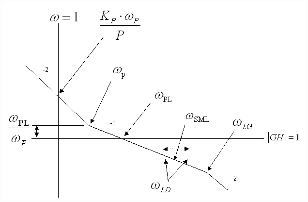
Fig. 6 Asymptotic Cascaded PL Bode Plot
The following equations describe cascaded PL tuning:
If the desired PL bandwidth (wPL) is less than the expected lowest speed loop bandwidth then no feedback forcing is required and:
- The PI lead frequency, wP is set to yield adequate phase margin at wPL, it is set to adjust phase margin at wPL such that the reasonable position loop damping is obtained (zPL defaults to 1) :
- The PI regulator proportional gain term is obtained as:
wP =  [rad/sec] (5)
 [rad/sec] (5)
 (6)
(6)
If the desired PL bandwidth (wPL) is higher than the expected lowest speed loop bandwidth then feedback forcing is required and the feedback lead/lag frequencies are set as:
iii) wLD is set to approximately cancel the instantaneous closed speed loop lag at wSML, it also moves with the desired position loop damping ( ) setting to adjust phase margin at the position loop crossover such that the desired position loop damping is obtained. That is:
 ) setting to adjust phase margin at the position loop crossover such that the desired position loop damping is obtained. That is:
 [rad/sec] (7)
iv) wLG is be set at 7 times the lead/lag lead frequency (wLD) The lag frequency must be less than 1.2/ [rad/sec], this is due to Nyquist sampling limitations:
 [rad/sec], this is due to Nyquist sampling limitations:
 [rad/sec] (8)
F. Comparison between AC and DC Drives
For most industrial process line position regulators the bandwidth of the SML is very low compared to the bandwidth of the torque/current loop of the AC/DC drive. In winders for example, this is due to large per-normal inertias reflected to the motor shaft at or near a full roll operating condition. The position loop bandwidth is constrained as a function of the speed loop bandwidth. The factor limiting speed loop bandwidth under these operating conditions is not dependent on the bandwidth of the current/torque minor loop, rather it is limited by torque jitter requirements as described previously [3]. For example:
Assume that the per-normal inertia of a system at empty core is 1 [sec] and at full-roll is 20 [sec] and the forward path gain is constrained to 60, the SML bandwidth at full roll is therefore limited to :
 [rad/sec] (9)
In this application a current/torque CML with a bandwidth of 150 [rad/sec], such as is found in a typical DC drive, or 3000 [rad/sec] such as would be found with an AC vector drive would make no difference to the performance of the speed loop, both technologies are orders of magnitude higher than the expected bandwidth of the speed loop. Similarly the performance of the position loop will not be enhanced by choice of either drive technology.
Some applications are designed with very low per-normal inertias. For example machine tooling, or high speed motion control robotic systems. In these applications the performance of the drive will impact the performance of the position loop. This is due to two factors.
- The drive technology used must be responsive enough and sample fast enough such that the SML loop bandwidth is not limited by either the bandwidth of the torque loop, or the sample rate of the SML.
- The use of feed-forward control techniques in these applications greatly enhances trajectory tracking accuracy. The greater the bandwidth of the torque loop, the more responsive the feedforward control, and consequently, the better the tracking.
For example: Assume that the per-normal inertia of a high performance robotic system is 0.1 [sec] and the forward path gain is constrained to 100, the SML bandwidth is therefore limited to :
 [rad/sec] (10)
In this application the use of an AC vector drive is recommended.
Guidelines described in detail in [3] can be used to determine whether the drive technology is limiting the performance of the speed loop, and consequently the performance of the position loop, in cascaded positioning applications.
G. Parallel Positioning Loops
Occasionally the use of an intermediate speed loop is not possible or not required in a positioning application. Examples of these systems are tooling applications, some cutter applications, and some drum surface-winding systems. If a PI regulator is used in these applications a lead/lag feedback forcing filter must be used. The use of a PI regulator in these applications is desirable because it leads to a type 3 loop which has zero steady state error to a ramped reference. This characteristic is highly desirable in tooling applications where ramped references are the norm. Some positioning systems (type 2 loops) use PD controllers, and do not require a feedback forcing lead/lag filter.
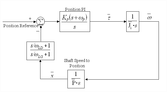
Fig. 7. Normalized Parallel Position Loop
An asymptotic Bode plot describing the tuning of the parallel position loop is shown in Fig. 8.
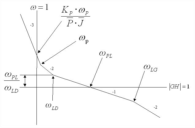
Fig. 8 Asymptotic Parallel PL Bode Plot
The following equations describe parallel PL tuning:
i) The PI lead frequency, wP is set to yield adequate phase margin at wPL, it is set to adjust phase margin at wPL such that a reasonable position loop damping is obtained (zPL defaults to 1) :
wP =  [rad/sec] (12)
 [rad/sec] (12)
ii) The PI regulator proportional gain term is obtained as:
 (13)
(13)
iii) wLD is set to approximately equal the PI lead frequency wL, it also moves with the desired position loop damping ( ) setting to adjust phase margin at the position loop crossover such that the desired position loop damping is obtained. That is:
 ) setting to adjust phase margin at the position loop crossover such that the desired position loop damping is obtained. That is:
wLD =  [rad/sec] (14)
 [rad/sec] (14)
iv) wLG is set at 20 times the lead/lag lead frequency (wLD) The lag frequency must be less than 1.2/ [rad/sec], this is due to Nyquist sampling limitations:
 [rad/sec], this is due to Nyquist sampling limitations:
 [rad/sec] (15)
It should be noted that the use of feedback forcing greatly increases the phase margin of the position loop and decreases overshoot to a reference step command. However, it also amplifies noise. A 20:1 lead/lag ratio will result in approximately 13[db] amplification of system feedback noise. This will degrade the value of the maximum possible loop gain KP(MAX). The same constraints on loop gain described above, and in [3] can be applied to these position loops.
An important observation from Fig. 8: The loop gain for a desired position loop bandwidth is directly proportional to both the per-normal storage, and the per-normal inertia of the system. This implies that if the per-normal inertia of the position loop varies, it must be computed and used to adapt the parallel position regulator gain to ensure that the position loop crossover and phase margin remain constant over the entire range of system operating parameters.
Cascaded Position Loop Load Shock Recovery Time:
A useful measure of cascaded position loop performance is load shock recovery time. This is the time it takes the cascaded position loop to return to a given percentage of maximum position feedback, after a speed step equivalent to a given percentage of rated speed is applied to the speed loop reference. This specification is strictly a method for specifying performance, and providing an understanding of the expected cascaded position loop command reference tracking, it will never occur in an application.
This specification can be expressed in terms of the ratio of speed loop bandwidth to position major loop bandwidth, as shown in Fig. 9. A family of curves is presented showing the effect of the ratio of speed loop bandwidth to position major loop bandwidth, on the position recovery time. The curves are for ratios of Speed Loop Bandwidths to position Loop Bandwidths of 1:1 to 1:3,with linearly spaced steps.
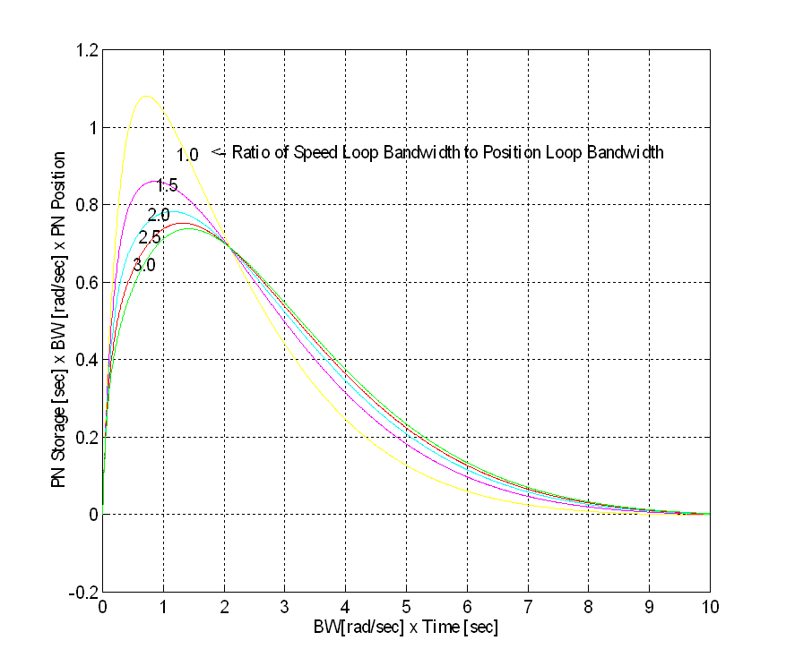
Fig. 9 Cascaded Position Loop Load Shock Recovery Time
The following procedure can be used, with Fig. 9, to calculate the time to recover to a position of DP after a DPMAX position deviation caused by an X% speed shock:
Step 2: Determine the bandwidth of the position loop (BW in Fig. 9 is equal to wPL) using the procedure defined in the previous section.
Step 3: Determine the maximum pos. deviation (DPMAX) for the specified speed shock
 (16)
(16)
Where Peak is taken from the appropriate curve in Fig. 9.
NOTE: If DPMAX < DP Step 4 can be skipped (i.e. the maximum deviation is less than the specified recovery position)
- Let DPPN = DP/PMAX, Where DP is the recovery position.
- Calculate the Y-Axis lookup value using :
- Calculate the time it takes to recover using Eq. 18
 (17)
(17) (18)
(18)
Assume that an adaptive position loop regulator has been used:
BWSpeed(min)
|
10 [rad/sec] Min. SML bandwidth (full roll) [rad/sec]
|
BWSpeed(max)
|
30 [rad/sec Max. SML bandwidth (empty core) [rad/sec]
|
BWMAX
|
10 [rad/sec] PL bandwidth [rad/sec]
|
X%
|
100% Percentage of rated Linespeed speed shock
|
VL(MAX)
|
2000 [ft/min] Top line speed
|
PMAX
|
10 [ft] Storage
|
DP
|
0.1 [ft] Recovery position [ft]
|
Step 1:  = 0.3[sec]
 = 0.3[sec]
Step 2: BW(Empty Core = 10 [rad/sec]
BW(Full Roll = 10 [rad/sec]
Step 3:  (peak from 3:1 curve)
 (peak from 3:1 curve)
 (peak from 1:1 curve)
Step 4: DPPN = 1/10 = 10%


This application shows that the turret winder has fairly stiff speed loops, thus providing the required inner loop performance to yield a very responsive position regulator. A very torsionally stiff, and backlash free drive train is required if this kind of a position loop performance is required. The following example is more realistic in large inertia winder applications.
Example 2, Paper Machine Winder Dancer:Assume that an adaptive position loop regulator has been used:| BWSpeed(min) | 0.5 [rad/sec] Min. SML bandwidth (full roll) |
| BWSpeed(max) | 5 [rad/sec] Max. SML bandwidth (empty core) |
| BWMAX | 1 [rad/sec] Desired position loop bandwidth |
| X% | 1% Percentage of rated Linespeed speed shock |
| VL(MAX) | 10000 [ft/min] Top line speed |
| PMAX | 4 [ft] Storage |
| DP | 0.4 [ft] Recovery position [ft] |
Step 1:
 = 0.03[sec]
Step 2: BW(Empty Core) = 1 [rad/sec]
 (peak from 3:1 curve)
 (peak from 1:1 curve)
Step 4: DPPN = 0.4/4 = 10%


From the above discussions it is clear that the performance of the cascaded position loop is intimately tied to the performance of the speed loop with which it is cascaded. Based on the discussion in the previous section, the performance of the speed loop in most process line applications is rarely impacted by the performance of the Drive torque or current loops. Performing the described analysis empowers the control system engineer to identify the performance needs of the drive for his/her application.
H. Torque Response Specifications and Position Loops
As described in previous sections, certain applications, such as automotive test stands, machine tooling equipment, or cut-to-length machines, the response of the torque/current regulator is critical for the adequate regulation of position, or motion control trajectory tracking. To qualify a particular drive for these applications, the drive vendor may supply specifications that apply to a torque step response, or they may specify bandwidth. [4] provides a detailed description of these response parameters and provides guidelines that enable a fair comparison to be made between differing vendor specifications.
IV. Conclusions
The performance of industrial control position and motion control applications are occasionally limited by the drive technology that is used. This typically occurs when the per-normal inertia, and per-normal storage of the system are small, and the mechanics of the system are very stiff, and well designed with minimal backlash and friction. Guidelines presented in this paper and in [3], [4] empower the cognizant control system engineer to make intelligent vendor choices when procuring a drive, based on the needs of the application in question.
References
[1] B. T. Boulter, "The Effect of Speed Loop Bandwidths on System Natural Frequencies in Multi-Zone Strip Processing Lines" , Transactions of the IEEE-IAS, pp. 126 - 134 Jan/Feb. 1999,
[2] B. T. Boulter, " Improving Bridle Low-Speed Regulation Using Cascaded Current Followers ", Transactions of the IEEE-IAS, pp. 1074-1082, Jul/Aug 2001,
[3] B. T. Boulter, " Applying Drive Performance Specifications to Systems Applications – Part I, Speed Performance ",Transactions of the IEEE-IAS, pp. 1082-1088, Jul/Aug 2001,
[4] B. T. Boulter, " Applying Drive Performance Specifications to Systems Applications – Part II, Torque/Current Regulation",Proceedings of the 36th IEEE IAS Conference, Chicago IL. Oct. 2001,
没有评论:
发表评论