By Dr Colin Hargis, Conformance Manager, Control Techniques Ltd
The Basics
AC variable speed drives have become widely used throughout industry during the last decade, because of their benefits in energy efficiency and controllability compared with uncontrolled fixed-speed AC motors. This has been confirmed recently with the UK government accepting AC drives as eligible for Enhanced Capital Allowances under its energy levy scheme.
In the power range of typically 370W to 200kW (measured as power at the motor shaft), compact VSD modules have become a commodity item manufactured in large numbers. Price competition is intense, and successful manufacturers operate in a world market. The drives are subject to the same EMC regulations as other industrial equipment, and there are difficulties when it comes to distinguishing between apparatus and installations, components and end-products for the purpose of EMC legislation. However this article concentrates on some of the technical EMC issues which are peculiar to drives.
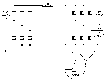
Figure 1 shows the essential elements of the power circuit in a VSD.

Figure 1: Basic elements of VSD power circuit
The incoming power, usually three-phase but in some cases single-phase, is rectified in the diode bridge to give DC which is smoothed by the L-C filter. The DC is then chopped up in the inverter to generate a three-phase ac output of variable voltage and frequency, using Pulse Width Modulation (PWM).
The inverter stage uses IGBT switching devices which offer fast switching (rise-times of the order of 50 – 200ns) at the high levels of voltage and current required (e.g. 600V and 2.0A – 500A). Switching frequency is typically in the range 2kHz – 20kHz. The inverter is controlled by a circuit using conventional electronic circuits with analogue and digital ASICs and microcontrollers or DSP, typically 16-bit with clock rates of 10 – 40MHz.
The construction always requires a relatively large heat-sink for the power devices, which usually forms the basic structure of the drive and is a convenient low-inductance base for EMC earthing of cable screens etc. The covers are typically precision plastic mouldings, the whole assembly being designed for volume manufacture with a high level of automation.
Figure 2 shows a typical drive family covering the power range 370W – 15kW, together with some optional input filters.
 |
| VTdrive ® www.vtdrive.com |
Figure 2: Control Techniques Commander SE range of drives, with optional input filters
EMC requirements
VSDs are used in large numbers, both for direct installation at their place of use to form part of a larger system and by OEMs producing complete industrial machines. For drives for direct installation, the relevant EMC standard in the EU is EN 61800-3, whilst the OEMs will generally prefer conformance to the generic standards which will be applicable to their end products, whether directly or through the TCF route. Therefore for commercial reasons the drive needs to meet the requirements of both. The requirements of the generic standards for the industrial environment and of EN 61800-3 are generally similar, but the latter does allow for higher levels of emission where the application is an industrial site which does not share its mains supply with domestic dwellings.
Immunity
The main requirement here is to conform to EN61000-6-2. Our experience at Control Techniques suggests that this is sufficiently stringent in most respects to ensure reliable operation in most practical EMC environments.
One exception is the surge test at the AC lines, where our experience leads us to require uninterrupted operation at 2kV line-line, 4kV line-earth; and no damage at 6kV in both modes. In parts of the world where thunderstorms are frequent and LV supplies are carried on overhead lines, the EN61000-6-2 requirements of 1kV line-line and 2kV line-earth are inadequate for a product which may be connected by a permanent connection to a point close to the power incomer.
Another interesting aspect is the means used to achieve immunity. Many drive users treat the drive as an essentially electrical component, in the same category as a contactor or a motor protection relay. It is not realistic to require the control wiring to be screened or treated in any EMC-specific fashion; it has to be simple open electrical wiring. The measures used to achieve immunity must therefore predominantly be built in to the drive circuit. This is mainly a matter of matching the response speed of the terminals to the intended application, for example the response time of a simple digital control input is only expected to be about 5ms. This permits us to use a simple passive filter to prevent reaction to fast transient or RF. Careful layout and detailed attention is needed to protect the processors from FTB and the analogue circuits from conducted and radiated RF.
Some ports are required to handle fast digital data, particularly shaft encoder inputs and data ports for industrial bus systems such as Profibus. Here the bandwidth cannot be restricted and careful attention is required to the provisions for cable screen connections, as well as to parasitic capacitance between the “noisy” and sensitive parts of the interface circuit.
Signal earthing policy and the treatment of cable screens is a continual source of misunderstanding in the drives industry. Drives cross the cultures of heavy industry and electronic systems and communications. In heavy industrial installations it has long been the practice to connect signal cable screens at one end only. There are good reasons for this, when there is a risk of power system fault currents flowing in the screens, but for high-frequency immunity it is well known that omitting one connection renders the screen virtually ineffective. This subject is discussed in depth in a recent book [1]. Tim Williams and Keith Armstrong provide a sound case for the use of multiple earth bonding of cable screens together with the provision of parallel earth conductors for electrical fault current. In most cases however the equipment vendor cannot influence their customers’ earthing practice, and must allow for a variety of approaches.
Users are becoming more sophisticated in this matter as various digital communications methods become more widely used, but the question of earthing versus isolation still often arises. For the manufacturer who needs to meet a variety of requirements with a world standard product, the solution is to offer full isolation of data ports, which can be used where necessary or bypassed.
In addition to the generic standard requirements, we have our own in-house tests. An important one is the test whereby the drive is required to operate in the presence of its own self-generated electrical noise. Although we provide comprehensive installation instructions to avoid excessive emission, users who do not follow the instructions still require the drive to work! A poorly installed drive with an unfortunate earthing arrangement can induce repetitive pulse currents of 1A or 2A peak and 100ns rise-time into signal cable screens. The generic standard tests do not cover this phenomenon, but a suitable test is readily created from a knowledge of the physical principles and experience of the kinds of errors sometimes made by installers.
Emission
Flicker
Drives do not of themselves generate flicker, other than the single switch-on surge as the DC capacitors charge via the surge-limiting circuit. It is always possible however for a user to create a system where the load is modulated, intentionally or otherwise, at a frequency in the sensitive flicker range. The drive supplier has to warn of this possibility.
Line harmonics
The input rectifier generates line harmonics, which are kept under control by the use of inductance in the DC link on the larger ratings, and by optional AC line chokes. Most drives are beyond the scope of EN 61000-3-2 so installations are considered on a case-by case basis under the electricity suppliers’ guidelines such as the UK G5/4 [2]. The main responsibility of the supplier is to provide harmonic current data to facilitate harmonic assessments under the guidelines. At Control Techniques we provide EMC data sheets for all of our products, which include harmonic current data.
The harmonic content of the input current of a drive can be reduced to negligible levels by the use of an active input stage, which uses another inverter similar to the output stage. This is controlled so as to produce a “back-emf” which follows the supply voltage waveform, so the only harmonics present are those already present on the supply – i.e. the load behaves as if it were resistive. The inverter stage of a drive is the most expensive part, so this technique is costly, but it may be the best solution where harmonic limitations are encountered.
Conducted Radio Frequency
The output of the inverter contains very high levels of energy in the frequency range 2kHz – 50MHz, which covers the range where RF emission is measured by the conducted method. It must be connected through the user’s cables to the motor, which may be nearby but may be up to 200m distant. Since an output filter sufficient to meet conducted emission standards would be prohibitively costly, it is usual to rely on the use of a screened power cable here. The installation therefore has no power output terminals which are subject to conducted emission limits.
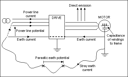
The power input of the drive carries a substantial RF potential, primarily because it comprises the return path for common-mode RF current which flows from the output cable cores through the capacitance of the cable and motor to earth. This is illustrated in Figure 3.

Figure 3: Main RF emission paths
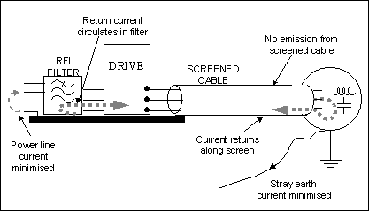
An input RFI filter provides a low-impedance return path to reduce emission into the supply. Figure 4 indicates how the filter and screened power cable complete the loop for RF current and prevent it from circulating outside the drive/motor system.

Figure 4: Complete drive, motor, filter system showing RF current paths.
RFI filters for VSD are quite difficult to design, because not only are the power currents high, but also the RF current produced by a drive exceeds that produced by most other products in common use. This is mainly because the stray coupling path through the capacitance of the cable and motor may be of the order of 10nF to 100nF, compared with the stray capacitance in the better-known sources such as SMPS where the capacitance is unlikely to exceed 100 – 200pF. The source impedance of the “noise” is low and a large current is available. This means that the ferrite cores of filter chokes can suffer magnetic saturation unless they are correctly designed and co-ordinated with the rest of the filter. The effect of saturation is to render the filter almost useless, since the inductance effectively falls by about two orders of magnitude. A given filter will have a limit to the total capacitance of the motor and cable which it can tolerate without a risk of magnetic saturation. Some of the lower cost filters have cable length limits of the order of 10m, which can severely restrict the application of the drive.
A filter for VSD use cannot be specified simply in terms of an insertion loss curve in a 50W/50W test, or even with the preferred 0.1W/50W test. It has to be tested with the correct VSD and representative motor and motor cable, to ensure adequate attenuation without saturation.
Designs have been refined over the years so that now they are available at a competitive price, but still the cost may represent some 5 - 10% of the drive cost.
Radiated Radio Frequency
The subject of radiated emission from micro-electronic circuits has been well covered in this journal and there is no reason to repeat the material here. Despite the use of a mainly plastic (not metalised) housing, careful attention to design details in the digital control circuits keeps radiated emission from this source to below the residential requirements such as EN61000-6-3.
The rise-time of the power-stage switching is such that the output energy content is tailing off rapidly from above about 20MHz, but it can still be responsible for excessive radiated emission in the 30 – 70MHz range. Provided that the earthing provision for the cable screen is adequate, the main emission route is through the imperfect screening of the motor cable. Some drive manufacturers have recommended specialised cables using one or more braided copper screens. Measurements at Control Techniques have consistently shown that low-cost steel-wire armoured cable, as widely used in the UK, gives equally good results. The reason for this appears to be that although the steel wire is a less effective screen (ZT is higher than for the copper braid), the losses in this frequency range are higher so that the actual current flowing in the screen is less. The cable is terminated by an impedance far removed from its characteristic impedance, so it is strongly resonant at some frequencies. The loss caused by the steel wire gives a useful degree of damping.
For the drive to be acceptable for general use there cannot be too much restriction on the type of cable used. The designers must therefore control the level of RF at the output terminals. Since the general trend is to make the IGBT devices switch faster, close attention has to be paid to their switching behaviour to prevent excessive RF emission. In many cases it is the reverse recovery behaviour of the inverse-parallel diodes which is the determining factor. All power semiconductor manufacturers claim to produce diodes which are both “fast” and “soft” in recovery, but quite subtle differences may be important. The arts of power electronics and EMC combine here.
Installation requirements
The use of a VSD inevitably involves the installer in providing some special EMC features, in particular the correct mounting of the drive module in relation to its input filter and screened motor cable. The manufacturer carries responsibility for ensuring that clear instructions are given to the installer. When drives first came into widespread use in the early 1990s the typical industrial control panel comprised a painted steel back-plate mounted into a steel cubicle which had no earthing provisions beyond the requirements for electrical safety bonding. Although the screening offered by such a cubicle is generally adequate, the inconsistent and inadequate RF earth bonding is not acceptable because the circulating RF currents are high. Installers were reduced to scraping off paint in the key contact areas. Fortunately the enclosure suppliers have now received the message and galvanised back-panels and convenient, sensibly-priced devices for multiple earth bonding are now readily available.
Further information on drives EMC, harmonics, and many other drives-related issues is given in the recently published Control Techniques Handbook [3].
References
[1] EMC for Systems and Installations; Williams and Armstrong; Newnes; ISBN 0 7506 41673
[2] Planning levels for harmonic voltage distortion and the connection of non-linear equipment to transmission systems and distribution networks in the United Kingdom. Electricity Association.
[3] The Control Techniques Drives and Controls Handbook; W Drury; IEE; ISBN 0 85296 793 4
没有评论:
发表评论